
Over the last 30 years many hardware concepts came out of use. Parallel data cables are not common any more. They got superseded by fast serial connections like e.g. SATA for traditional parallel IDE. One of the longest lasting standards, the 34 pin floppy controller connector, came out of use too. Fortunately, not too long ago. Thus we were able to reproduce a connector cable for the 8″ drive from existing parts out of the dust bin of scrapped electronic. The mint condition 8″ Mitsubishi M2896-63-02M double side (DS) double density (DD) drive featuring a 50 pin edge connector arrived and was to be connected to the PC. Fortunately, there are significant similarities in the 8″ 50 pin and later day 34 pin 5,25″ and 3,5″ connections.
Here is a method to create a 50 pin edge connector from two 34 pin FDD edge connectors. Start with obtaining two good 34 pin edge connectors for a 5 1/4″ Floppy. Time to revive some old skills from earlier days. Fortunately, this challenge got taken by Bart, the husband of Denise.
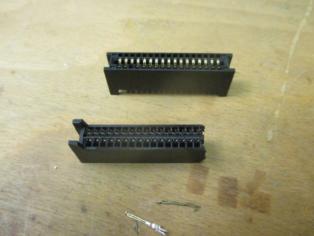
Select one connector and locate the key between pin 3 and 5, then pull out the two pins, 33 and 34, (furthest away from the key). Cut through the holes created and file/ sand the cut edge flat until the metal from pin 31 just becomes visible in the plastic.
Take the second 34 pin connector and hold it facing the edge side. Locate the key between pin 3 and 5. Count from the opposite end from the key, 9 positions (or 18 pins, 9×2) towards the key. Count and check again before pulling out the pins at the 10th position and cutting through the plastic there. You now should have a connector with 32 pins and a key, and one of 18 pins without a key.
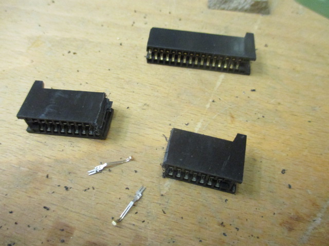
Alea iacta est (the dice is cast), no going back now (see Step 2 picture)! The section on the left will be used. Follow same filing/sanding procedure as in Step 1.
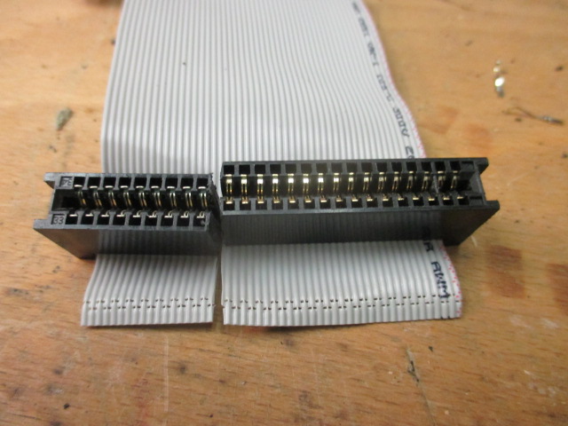
Here the two sections are fitted to the cable. The tear in the cable is for stress relief as it is virtually impossible to exactly line the two sections up on the cable. The cable was first laid over the pins of the larger part of the connector while lining up cable number 1 at the end. It was covered with one of the old pressure/alignment pads and gently tapped down so the pin connections could be made. The process was repeated for the smaller section. When both were in place, the cable was pressed home by gentle pressure of my thumb nail, running it along all rows of cutting edges.
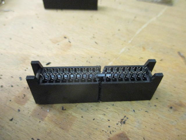
Because the larger part of your new connector is centred by the key at the beginning, the first 32 pins will line up perfectly. The second section can be a little off centre, depending on your filing/sanding accuracy. The space between contacts is approx 2 mm so there is plenty of room to make contact and accommodate for a slight offset in the second (18 pin) part of the connector. The SCSI cable had the required 50 pin socket/connector required for the other side already attached to it. It simply got reused to be plugged in into the dbit adaptor.
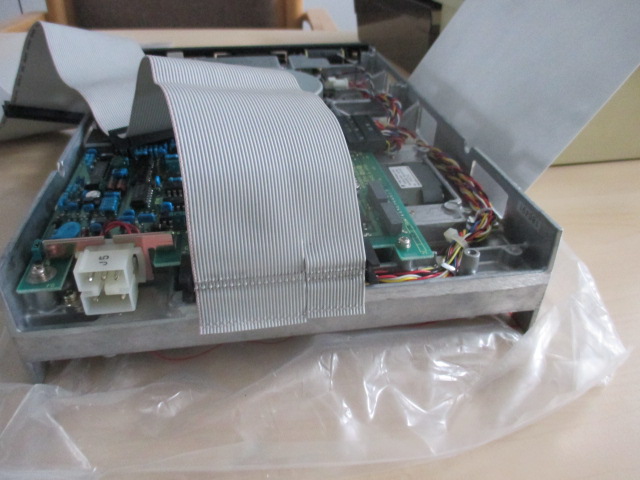
The cable has been attached to our half height Mitsubishi 8″ disk drive. Perhaps a rubber band around the two halves may be beneficial to keep them together and ensure that the metal contacts fit properly. Now we just needed to wait for the cable adapter board to actually connect to the PC and the step-up power module to support for the required 24V of the drive’s motor. The power connector socket is well visible left of the connected ribbon cable in last picture.


